Now that NeoVGA is more or less finished, I can get started on my Nintendo 64 line doubler. Like NeoVGA, it takes a 15Khz video signal digitally and double-scans it to produce a 480p signal compatible with a VGA monitor.
First and foremost I have to give credit to Tim Worthington and his original N64RGB project. From his schematic I was able to get information about the N64 pixel format and its four states.
Unlike the Neo-Geo, the Nintendo 64's pixel bus is not as straightforward. With a 50Mhz clock, the data for a single pixel is output over four states. The first uses the 7 bits as a bitfield for sync information, while the remaining three states are red, green, and blue.
The first thing I did was write an N64 pixel decoder in VHDL so I can have access to a parallel RGB bus for reading pixel data. I hoped it wouldn't be needed, but the VHDL generated from Tim's schematic capture was huge and pretty messy (no criticism on his part - that's what happens with a schematic capture). Also, the original design would have output red before green, and green before blue, etc. giving a bit of a horizontal blur to the image.
I don't have any DACs on hand, and I'm not using the usual Altera DE2 board with an on-board VGA DAC, so I breadboarded a crappy one using a resistor network. For the original RGB signal, it is fast enough and doesn't suffer serious interference:
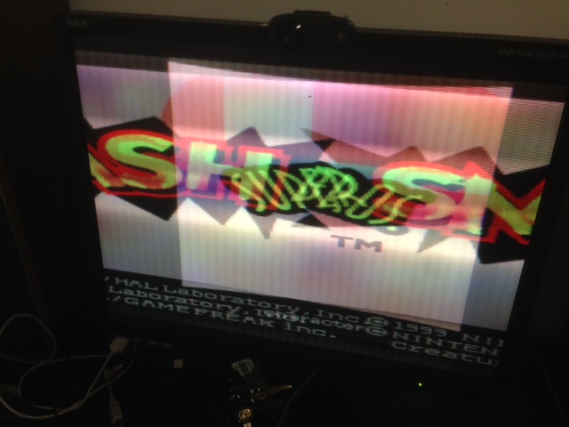
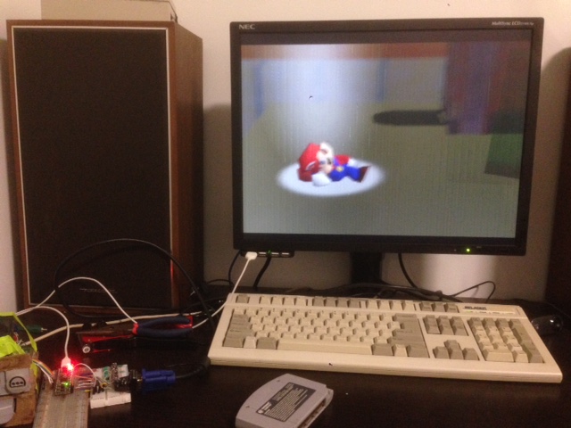
As I connected each bit, starting at the MSB going down, the image gained more detail. Here is how it looks with only 8 total bits connected:
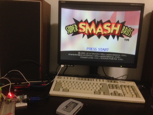
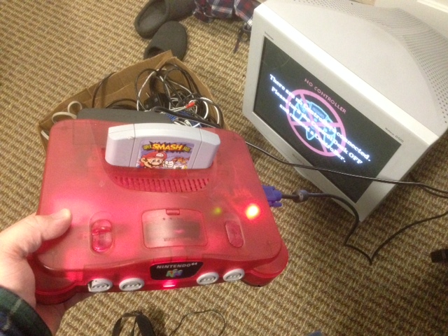
At this point, all of the work is just getting it to display on my RGB monitor. The signal is still standard resolution, with an effective 12.5Mhz pixel clock which allows for a visible picture width of about 640 pixels.
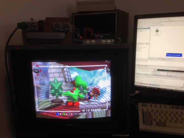
From here on, I thought the project should mostly be like NeoVGA, just with different constants for line length and number of lines, etc. So the first thing I did was use a rough guess of how long each line was, and assume a pretty normal 262-line image. By counting clocks, I got the FPGA to generate some suitable VGA timings and for now fed it the raw RGB data. But hey, it lets us see that the data is being captured properly and that the VGA output is doing anytihng at all:
As a result, the image is stretched to double its intended width. Once I verified that the Vsync signal I was decoding worked, I synchronized the VGA output's Vsync to that of the Nintendo 64, though I changed the duration to better match the de-facto standard of two lines (at 480 lines per frame). This kept the image from rolling vertically.
After that, I set up my big line buffers. Unlike NeoVGA the resource consumption is much larger - each line is about twice as long (to support 640 pixels) and 21 bits wide. That's much more than 384 pixels long, 17 bits wide. Here's the first result after I tried the line doubling:
It's close! The skew is from the line length being incorrect. After some trial and error I realised that the Nintendo 64 doesn't seem to output an even number of "pixels" per line (where a pixel is four clock deltas), and seems to end on a half pixel.
The first solution was that I synchronized my N64 pixel counting back to zero when an Hsync signal is recognized from the system. That fixed the skew, but because of that "half pixel" the line length was off by one when the line was being read out the second time (for the line doubling). Keep in mind that with these line doubling timings, half an N64 pixel equals one VGA pixel in duration.
I spent a lot of time tweaking the line length and buffer size to try and fix it, but it would always be slightly off, dancing around the right value. The fix here is a bit of a hotfix and I'm not that happy with it in the long term, but I simply delay the second line reatout to compensate for it.
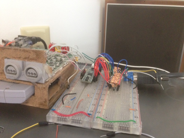
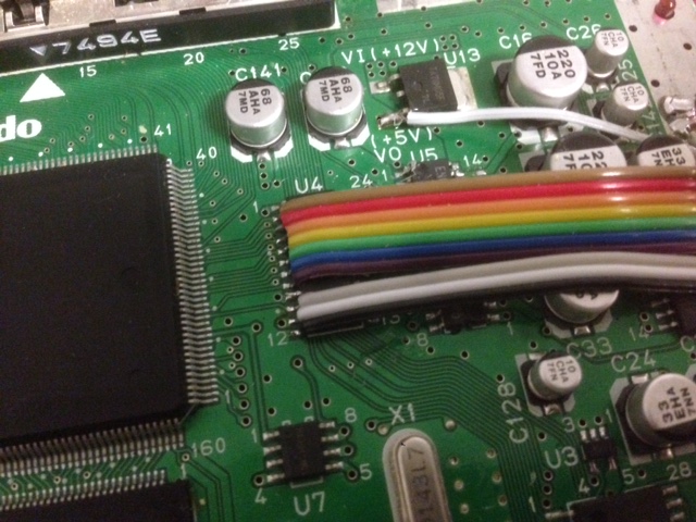
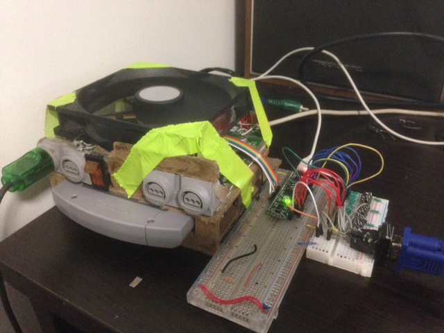
Now that the image looks pretty stable and the lines are clear, it's time to neaten up the wiring. Some colored ribbon cable makes the system connection look nicer:
The FPGA is pretty small, so I grabbed some protoboard and threw a board together using my crappy ladder DACs so it could fit inside the N64 - the intention was to take the system around and try it on a few other monitors.
Inside the system, though, the interference got really bad - it would lose sync sometimes, and there were harsh jailbars on the image. What's interesting is that the interference itself was the raw data from the N64, so a faint impression of the image at double width was visible.
Well, back to the drawing board. I took it out, and built a cleaner DAC with smaller resistors at higher accuracy. The interference is still there, though it's not as bad. It (understandably) gets worse with each bit added.
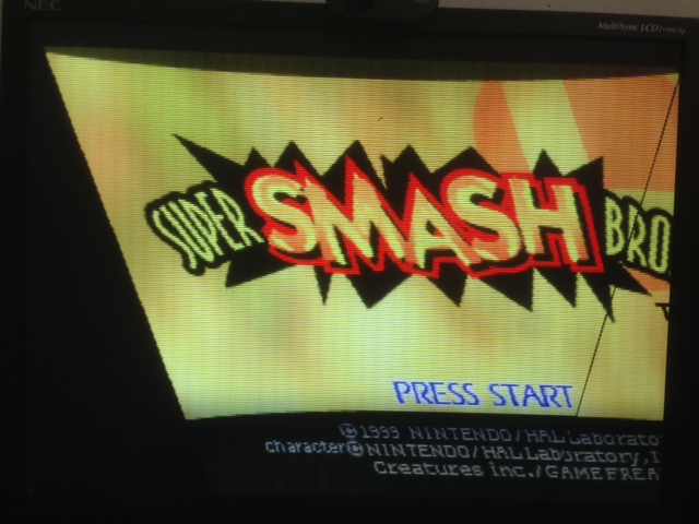
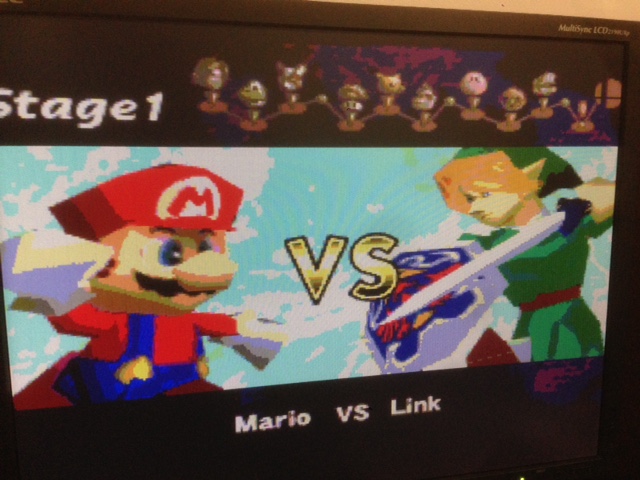
At just two bits per channel, the image is pretty clean:
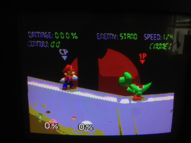
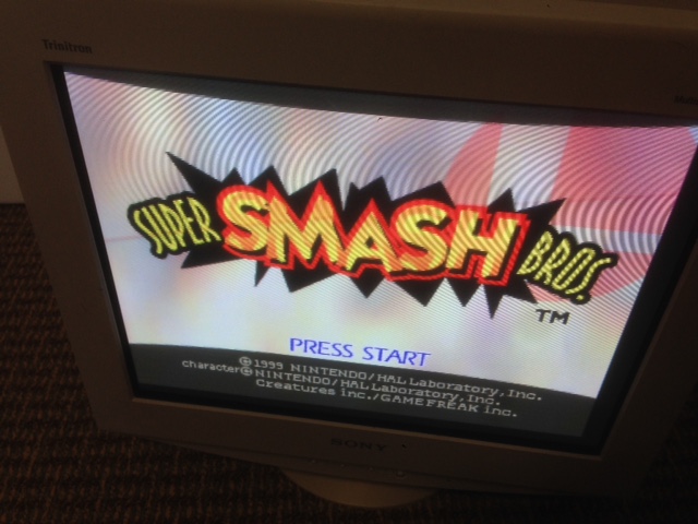
The interference is more visible on these pictures with all the bits:
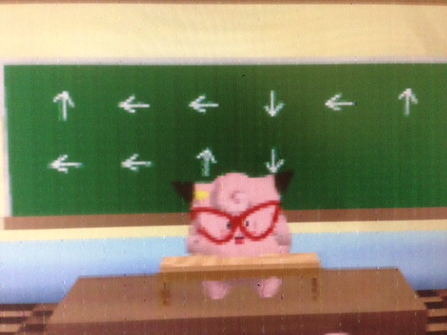
The regular vertical lines aren't in the image, exactly - the limited resolution of the monitor's ADC exagurates the effect. By adjusting the phase I can "move it around" on the screen.
I'm going to get a real active DAC intended for analogue RGB outputs and wire that up, which should solve the issue. I think it shows up much more on the LCD monitor because the impedance is higher, reducing the current coming from the output lines.
I've been looking at doing DVI output, and I don't think it should be too hard - the Spartan 6 dev kit I'm using has a PLL I can use to generate the TMDS clock, so as long as I don't run out of resources on the device it might be possible, which would remove concerns about analogue interference.
Back to main index