Look at this NetTV found at a local shop. It's huge!!!
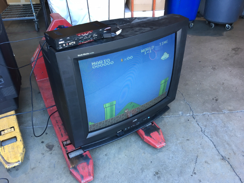
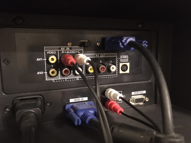
The NetTV rules as a large CRT monitor. It has a VGA port intended for computers! It can support 480p up to 768p through the VGA input. You can use a Dreamcast at 640x480 progressive scan. Modern consoles can be connected without too much trouble, and hooking a PC up and watching a movie actually looks quite good.
It also has traditional composite and s-video inputs. The best part is that the composite and s-video ports have the TV swithing scan rates down to 15KHz. That means they can do native 240p and 480i, without a line doubler or scaler!
This TV can be modified to accept low-res 240p / 480i RGB signals as well, though not through the same VGA port.
You might expect that a TV like this would naturally accept RGB at 240p. Sadly, giving the VGA port anything below 480 lines results in it just going into standby. The VGA port acts like a common VGA PC monitor. Even seperate H/V sync didn't make it happy.
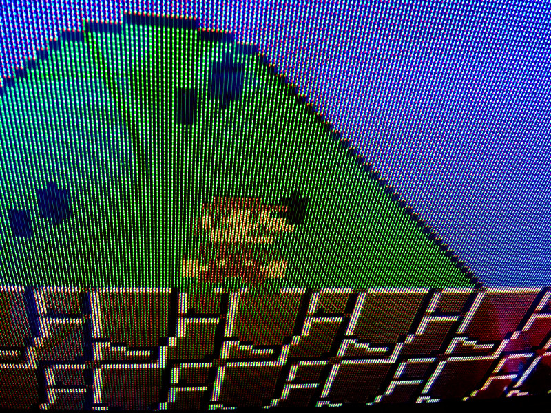
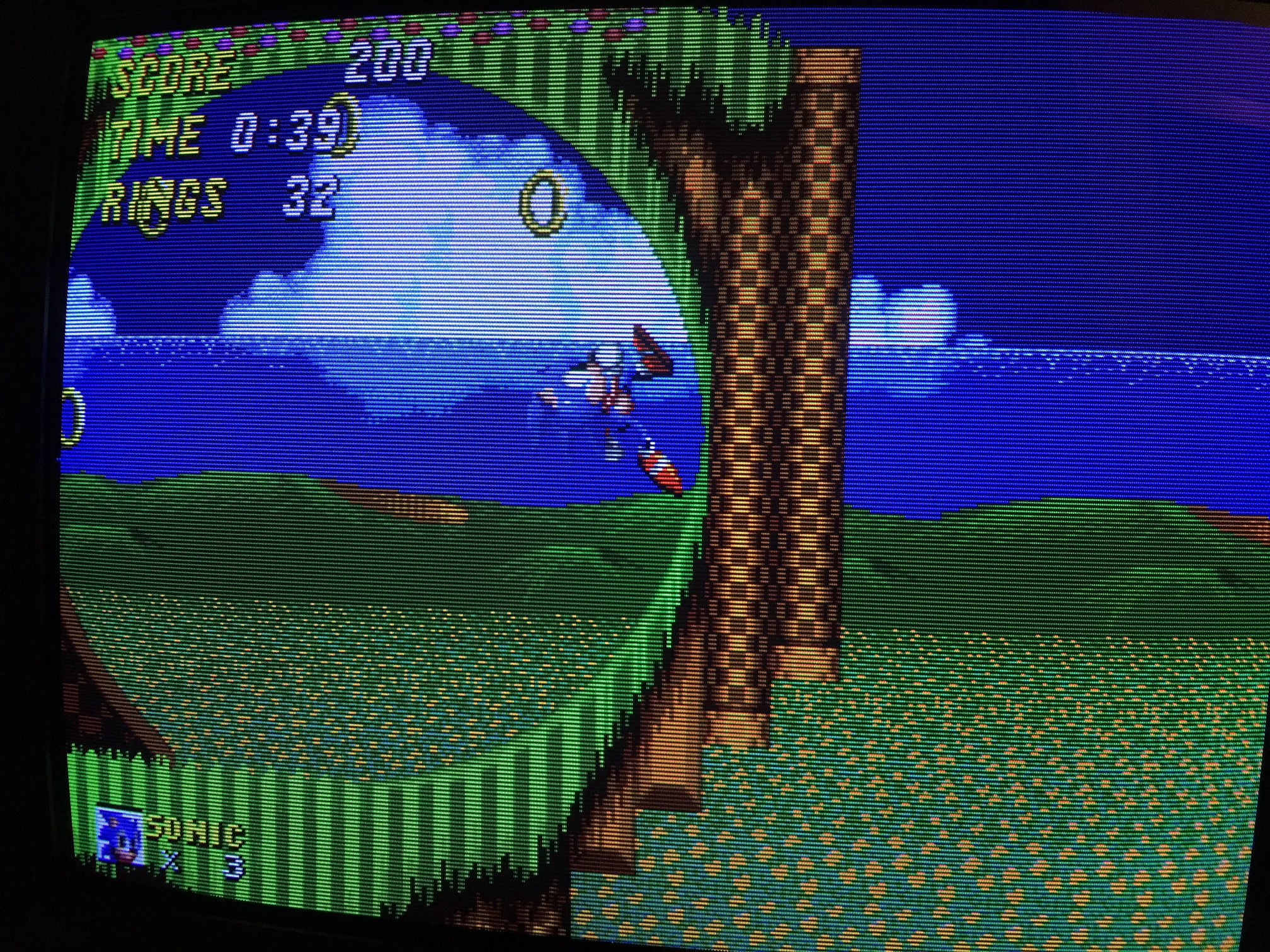
A quick solution is to use a line doubler, in this case an XRGB3. Feeding line-doubled RGB to the scaler gives us a working 480p signal, which the TV accepted without any issues. The resulting image looks great, though the edges are a little too rectangular for my taste when I know this set has juicy native 15KHz rattling around inside it.
Of note is that the composite video inputs look abysmal, easily the worst composite I've seen on a set from the nineties.
Like many TVs, this one has an OSD. I figured it would be worth trying to inject RGB into the jungle IC when the TV is in 15Khz mode.
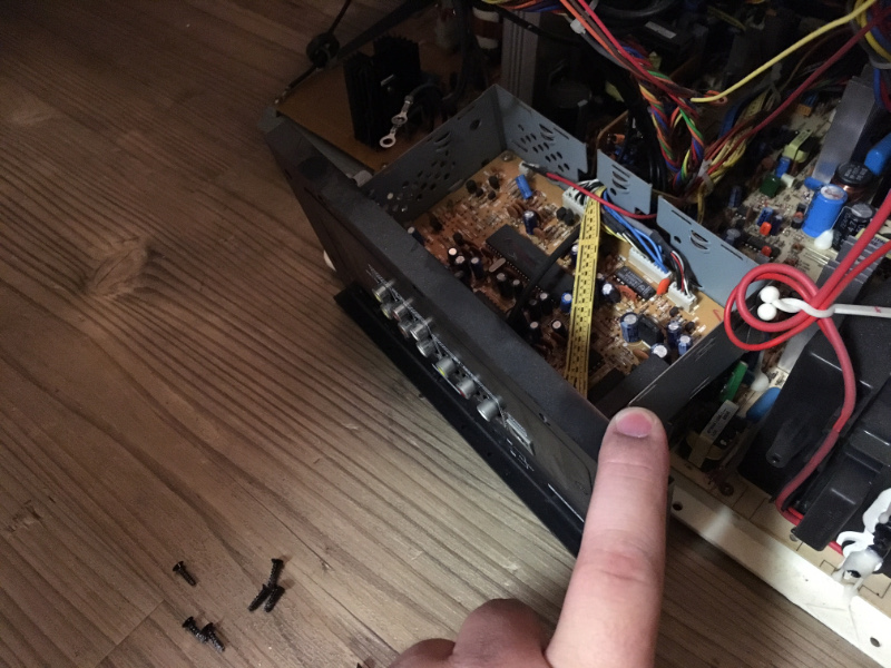
I cracked the TV open (with an absurd 18" screwdriver) and found that it wasn't dusty or grimy inside. I don't think this particualr set saw a lot of use.
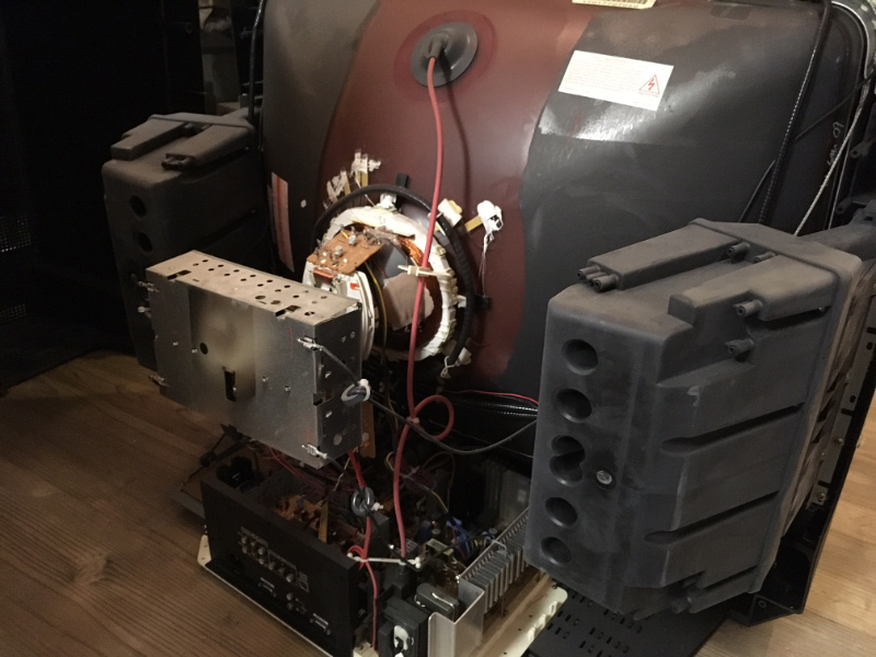
Towards the bottom, near the inputs, is a daughterboard right behind the low-res inputs. On it is a Phillips TB1227BN jungle IC. Great news: this jungle not only has an RGB input for the OSD, but it actually has a second unused RGB input, which is intended for closed-caption decoder outputs.
I pulled the daughterboard and brought it to the workbench. I did not have to touch the main chassis of the monitor at all as it was not necessary. I traced out the pins for the unused RGB2 input. The blanking line, YS2, was pulled low through a high-value resistor. The RGB2 input lines had all the termination necessary for a closed-caption board, and they run up to a a header in the corner.
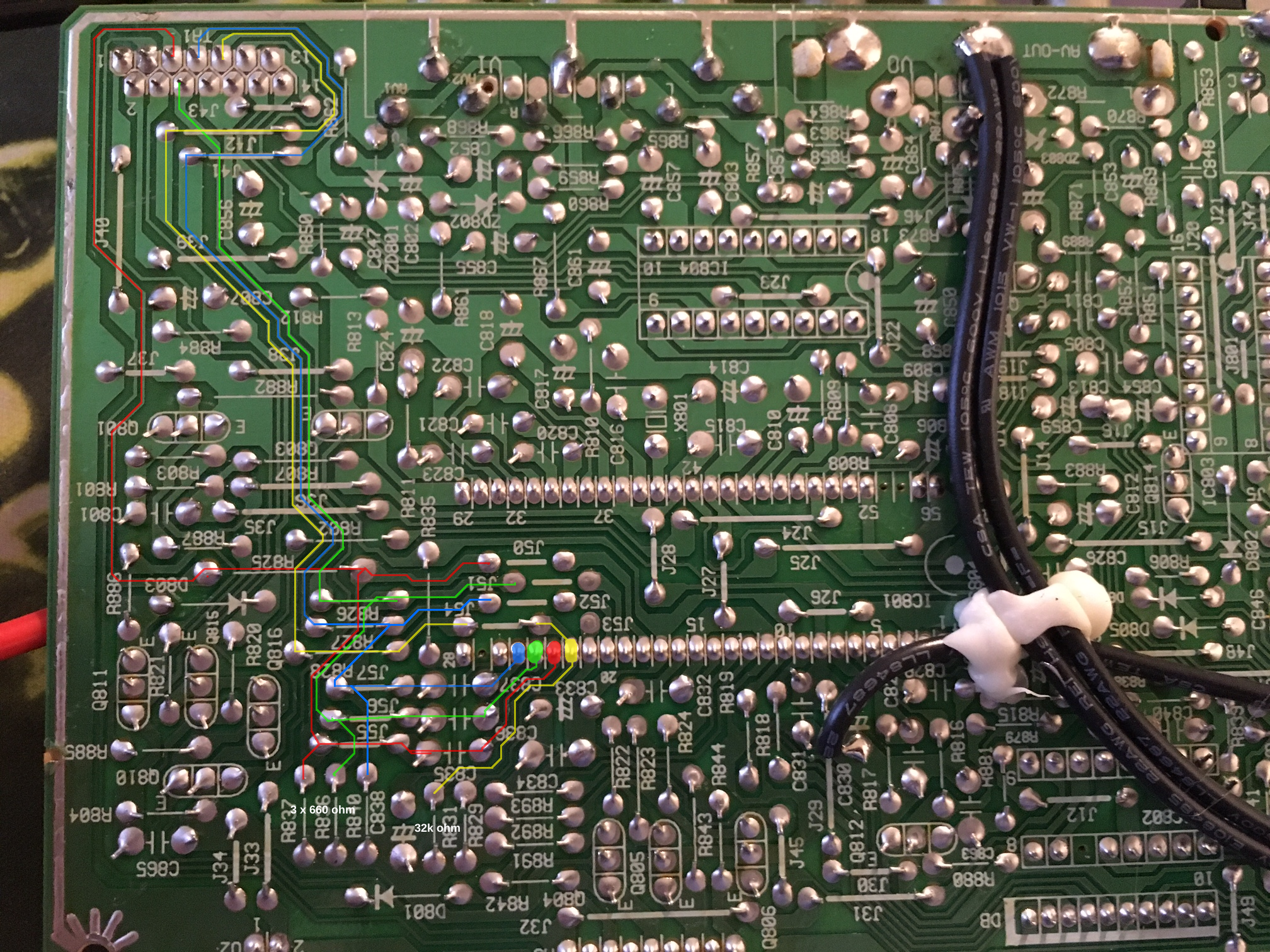
The board terminates the RGB inputs with 680 ohm resistors. I replaced these with 75 ohm resistors. I also tied YS2 high through a low-value resistor (75 ohms was fine) and attached this to a switch to let me use the composite inputs if I need them. I wired a port, bringing RGB to the resistors I had added for termination. I ran sync to the Composite 1 input through a 680 ohm resistor, as it is 75-ohm terminated and I wanted to reduce the current sunk from a TTL sync source.
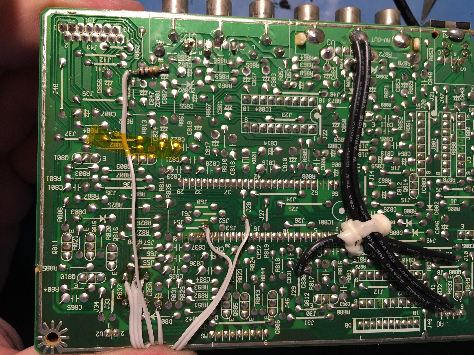
After all that, it worked on the first try (well, almost - I did the 75-ohm RGB termination change after having tried it as-is first). All I had to do was mount the port to the back alongside my switch, and I was done.
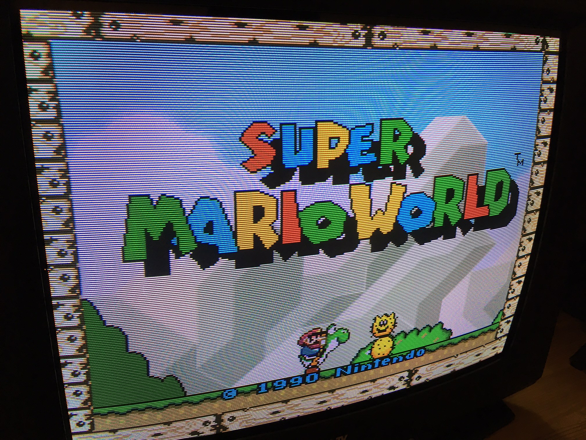
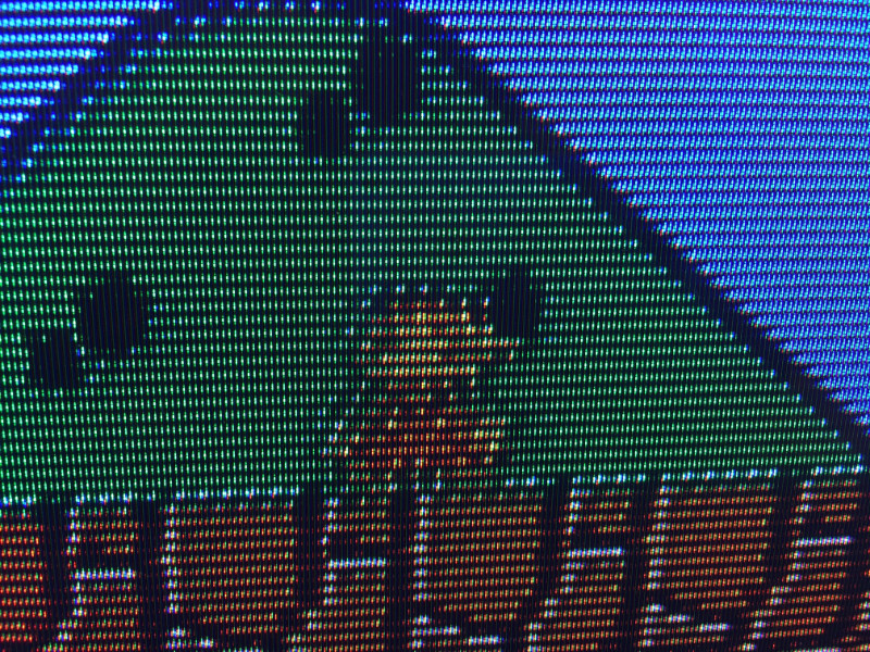
An extra nice feature of this RGB hack is that the OSD works on top of the RGB video without any extra work. If I was using SCART, I could use the SCART port's +5V signal to trigger YS2 to force blanking, which would make the TV automatically switch to RGB when given a signal and otherwise act completely normal. I don't run SCART, though, and my video cables do not supply power.
Forgive my handiwork here as I am not great at using the dremel (though the real problem is that I don't have the correct cutting bits for this!)
Back to main index